Learn about metal laser powder-bed fusion:
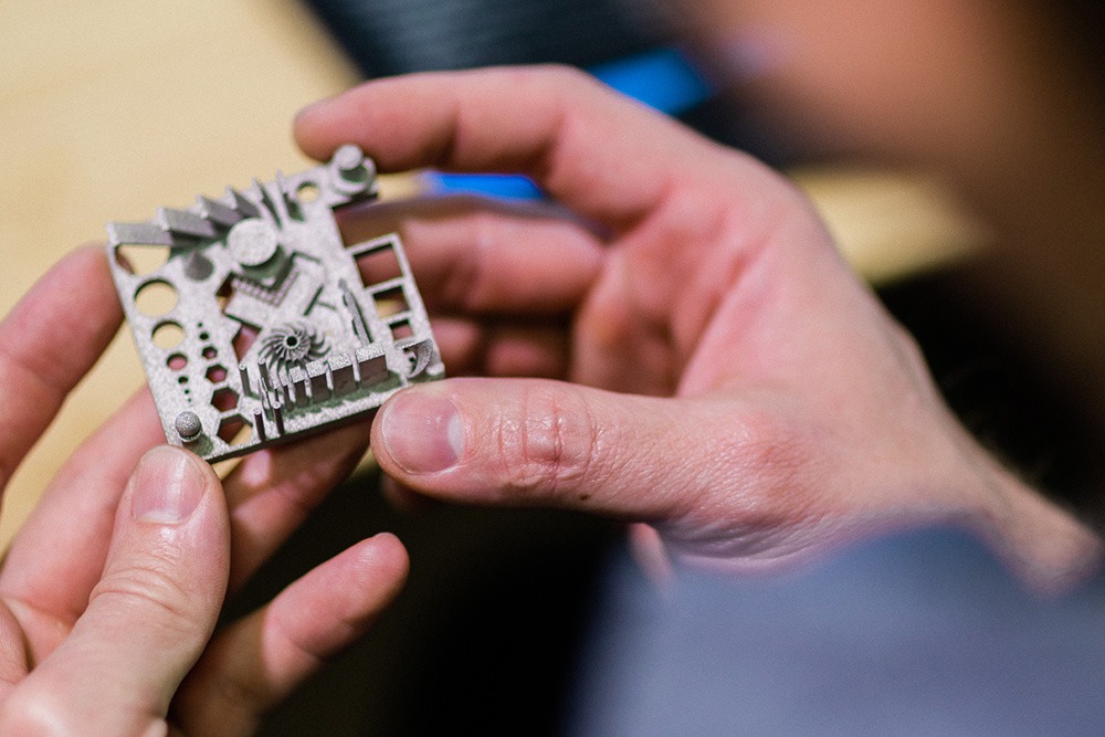
Metal Powder-Bed Fusion—also known as Selective Laser Melting or Direct Metal Laser Sintering—is an Additive Manufacturing process using a laser to melt consecutive layers on a metal powder-bed. The powder fuses into the finished dimensional part, incorporating complex internal and external geometries.
Removal of part from build plate with wire EDM, bandsaw, or flush cutting tool
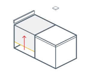
Feed cylinder increments up placing powder in front of the recoater.
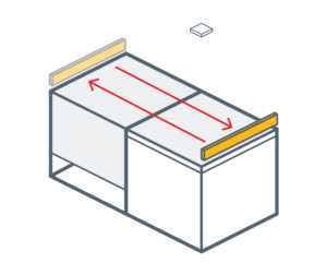
Recoater moves across the feed cylinder delivering powder to the build cylinder.
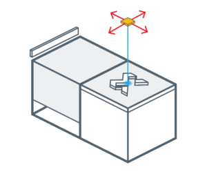
Laser fuses the cross section of the part.
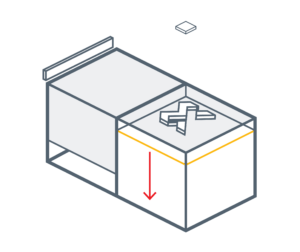
Build cylinder increments down one thickness layer.
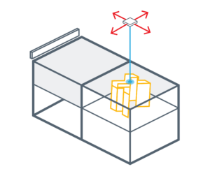
The process is repeated until the volume of the part is fully built.
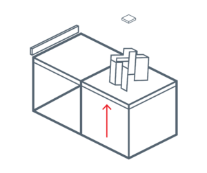
The build cylinder raises up and the build plate is removed.
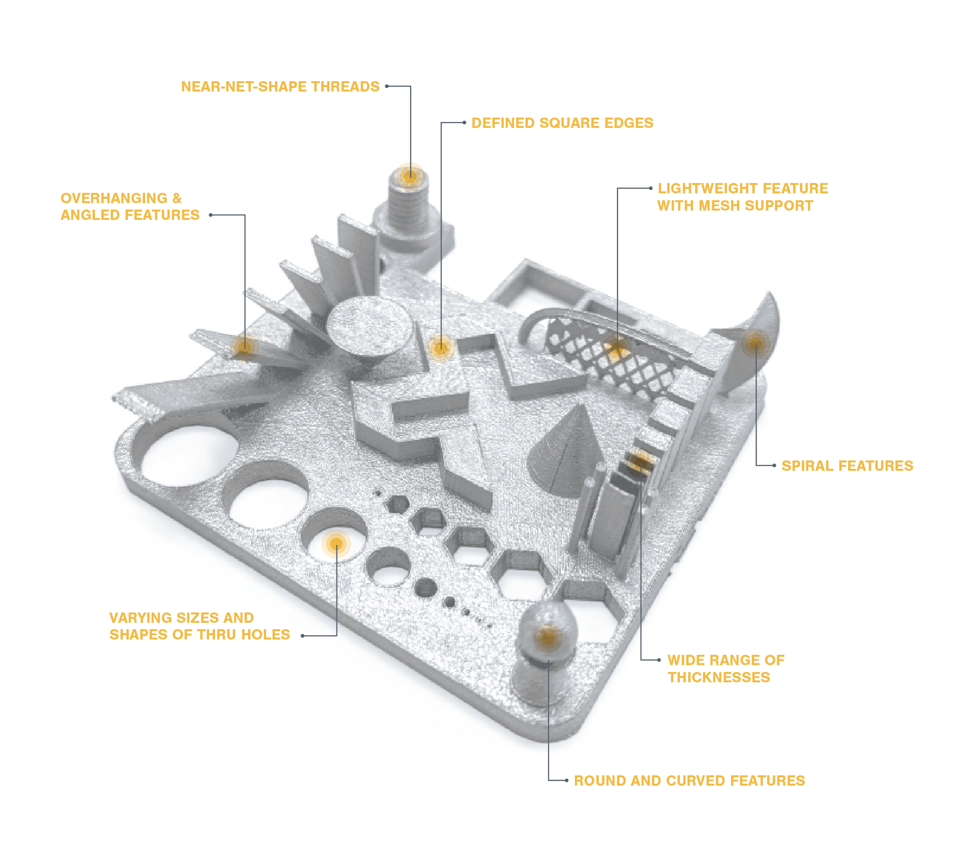
Additive Manufacturing systems print near-net-shape 3D components from Computer Aided Design (CAD) data. Compared to traditional machining and assembly processes, additive manufacturing significantly simplifies manufacturing and can produce components with highly complex features and all-in-one assemblies.
Metal Powder-Bed Fusion enables manufacturing of complex geometries with many features not readily obtainable by conventional subtractive manufacturing processes such as machining and casting.
Design of components for Metal PBF manufacturing requires consideration of several key guidelines. 3D CAD programs such as AutoDesk Netfabb® and Materialise Magics have features to assist in your design including modules devoted to Additive Manufacturing.
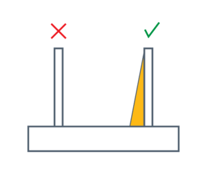
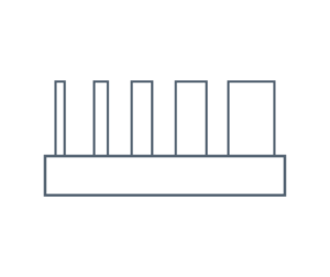
Tall, narrow features should have a maximum height:width (aspect) ratio of 8:1. Features with greater aspect ratios risk damage by the recoater during powder application. Adding a gusset to the component design will strengthen the feature and minimize damage.
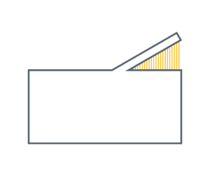
Flat ceilings larger than 1 mm (0.04 in.) will require a solid or mesh support. Fillets can also be added to prevent warpage out of the build plane.
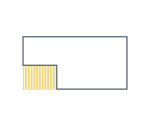
Solid or mesh mechanical supports can be added to optimize anchoring, minimize wall distortion from thermal gradients, support overhanging geometry, and provide solid anchoring between the component and the build plate to eliminate component movement during printing. The supports are removed after separation of the component from the build plate. Extra care should be taken when removing supports from thin walled parts; the process of removing the supports could potentially warp the parts.
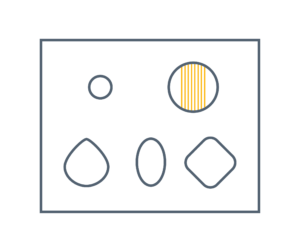
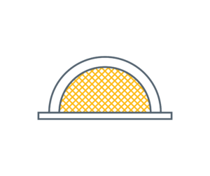
Horizontal holes with diameters less than 5 mm (0.2 in.) can be printed reliably without internal support. Larger holes will require an internal mesh support or design change. Changing to a tear drop, oval, or square shape will eliminate the need for internal supports.
Typical minimum wall thicknesses range from 100 to 200 microns
(0.004 to 0.008 in.).
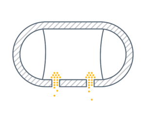
Holes are required to allow powder to escape from enclosed printed structures. A minimum hole diameter of 3.0 mm (0.12 in.) is recommended. Multiple or larger holes will increase the speed of powder removal.